Thank you for your quick response!
Can you give a better description of what you are doing? Do you have screenshots?
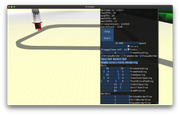
Sure I can try. I am trying to create an animation showing how a 3d printer would create an object layer by layer.

Above is an image of the 1st layer.

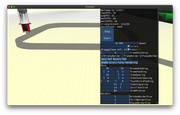
Above is an image of layer 3 or 4. In this example, the printer is creating a rectangular structure with curved edges.
Are you using always the same material or different ones?
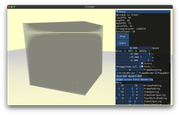
At this time I am always using the same material which just colors the cube grey:
Code: Select all
material MyMaterial1
{
    technique
    {
        pass
        {
            texture_unit
            {
                colour_op_ex source1 src_manual src_current 0.52 0.52 0.48
            }
        }
    }
}
If you have enabled SDK Trays check the number of batches in the performance panel
I don't have SDK Trays set up but I can look into that and update the post later if that would be helpful.
Currently, I am creating this animation by placing a grey cube under the nozzle each frame.
I create the cube using the manual object class in a setup method and convert the manual object to a mesh:
Code: Select all
Ogre::ManualObject* manual = mSceneMgr->createManualObject("Cube");
    manual->begin("MyMaterial1", Ogre::RenderOperation::OT_TRIANGLE_LIST);

    Ogre::Real len = 1;
    Ogre::Real z = len;

    // Define first 4 points that we will use as the first 4 vertices of the cube
    Ogre::Vector3 topLeft(-len/2, len, z);
    Ogre::Vector3 topRight(len/2, len, z);
    Ogre::Vector3 botRight(len/2, 0.0, z);
    Ogre::Vector3 botLeft(-len/2, 0.0, z);

    // Create first 4 vertexes, which make a plane at z = 0.
    manual->position(topLeft);
    manual->position(topRight);
    manual->position(botRight);
    manual->position(botLeft);

    z = 0;
    topLeft = Ogre::Vector3(-len/2, len, z);
    topRight = Ogre::Vector3(len/2, len, z);
    botRight = Ogre::Vector3(len/2, 0.0, z);
    botLeft = Ogre::Vector3(-len/2, 0.0, z);

    // Create last 4 vertexes, a copy of the first 4 but now at z = len.
    manual->position(topLeft);
    manual->position(topRight);
    manual->position(botRight);
    manual->position(botLeft);

    // Create the 5 faces we need to make the cube
    // front
    manual->quad(0, 3, 2, 1);
    // back
    manual->quad(4, 5, 6, 7);
    // top
    manual->quad(4, 0, 1, 5);
    // right side
    manual->quad(1, 2, 6, 5);
    // left side
    manual->quad(0, 4, 7, 3);

    manual->end();
    manual->convertToMesh("Cube");
Then each frame I get the position of the nozzle of the printer and place one of these cubes under it with this code:
Code: Select all
virtual bool frameRenderingQueued(const Ogre::FrameEvent& evt) {
	SceneNode* cartNode = mSceneMgr->getSceneNode("cart_node");

	// Grab the position of the cart in Ogre coordinates.
      cartPositionOgre = cartNode->convertLocalToWorldPosition(Ogre::Vector3(0, 0, 0));
      //  Translate into World_Node coordinates.
      cartPositionWorld = Ogre::Vector3(cartPositionOgre.x, -cartPositionOgre.z, cartPositionOgre.y);

      // Create a block under the nozzle
      Ogre::Entity * ent = mSceneMgr->createEntity("Cube");
      Ogre::SceneNode* node = mSceneMgr->getSceneNode("world_node")->createChildSceneNode(cartPositionWorld);
      node->attachObject(ent);
      node->translate(-5.497, 7.05, -47.654 + amt, Ogre::Node::TS_PARENT);
}
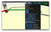
On top of the performance issues, the other flaw in this strategy is that if the frame rate drops low enough there will be visible gaps in the structure, like this:

I know there must be a better way to do this, one thing I am currently trying is to use manualObject::beginUpdate to extend the Cube mesh each frame but I am not sure if this will impact performance when I finish (It will stop the gap problem at least).
Hopefully, now you have a better idea of what I am trying to do (sorry for the long post). If you have any ideas/suggestions/direction on a better way to do this, or if OGRE is simply not suited for this task please let me know!
Things I am considering: manualObject::beginUpdate, OgreProcedural::Extrude
https://wiki.ogre3d.org/Ogre+Procedural ... ry+Library, maybe some kind of animation?
Again, thank you for the help!